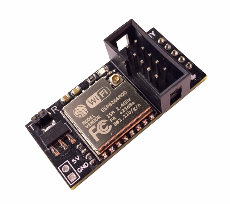
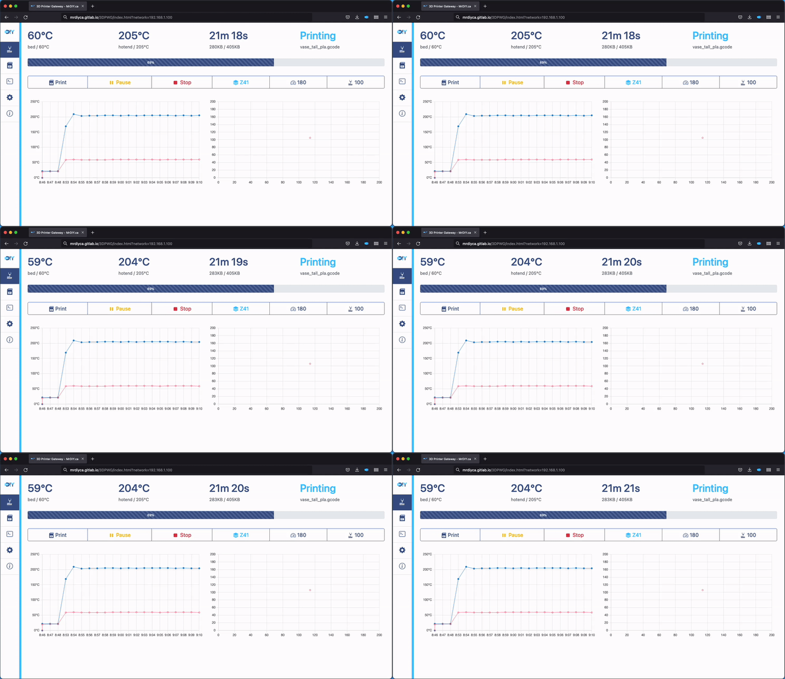
The companion board connects to the 3d printer’s power supply and its serial port. Using MrDIY’s 3D printer dashboard, this board can control and view realtime info about the printer. Two wires are required to be manually soldered. It has been designed and tested on an Creality Ender3 V2 but should work with other 3D printers. running G-Code ( ex: Marlin firmware).
Setup
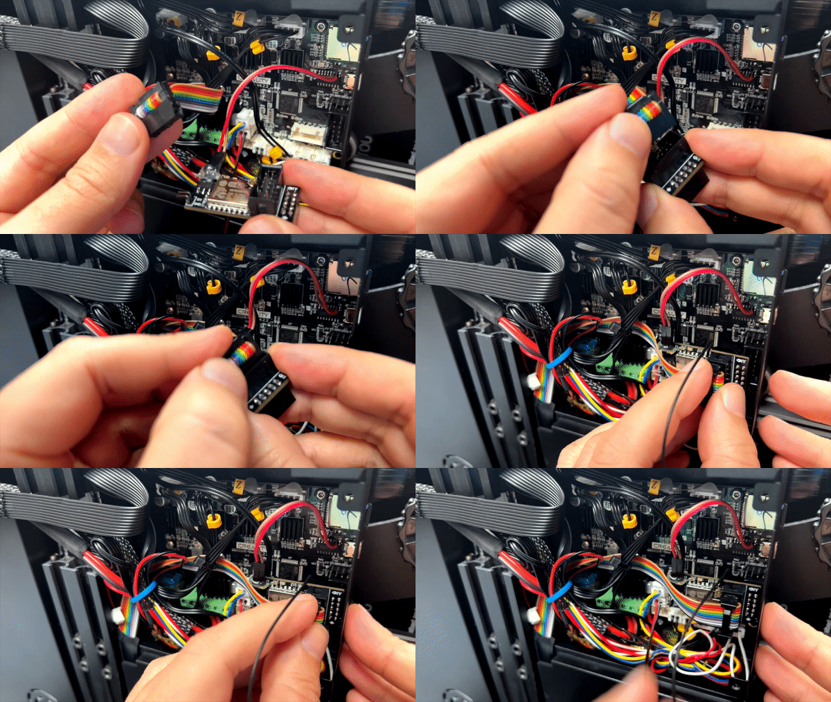
1) Insert the board between the LCD cable and the 3D printer’s motherboard as shown below.
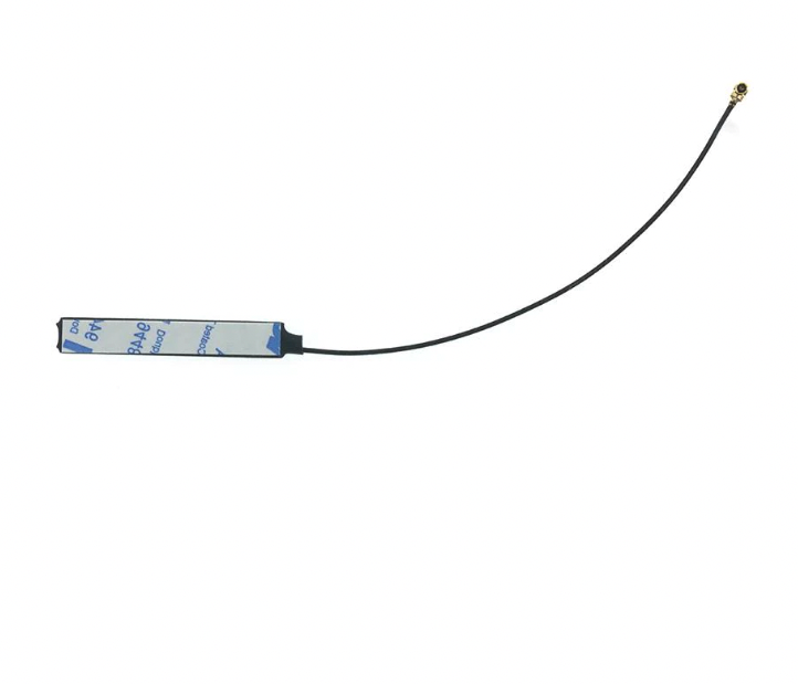
PS: do not stick the antenna to the metal frame.
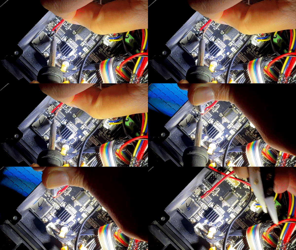
2) Solder the Rx and Tx table to the printer’s Tx and Rx ( you can use the CH340 hack as show below).
3) Power up the 3D printer then connect to ‘MrDIY 3DPWG’ access point ( the password is mrdiy.ca) and follow the instructions. It will ask for your Wi-Fi’s credentials. After it connects, record the IP address. This can usually be found on your router’s DHCP table.
4) Visit http://mrdiyca.gitlab.io/3DPWG/index.html and enter the IP address of the board recorded above ( ex: 192.168.3.160)
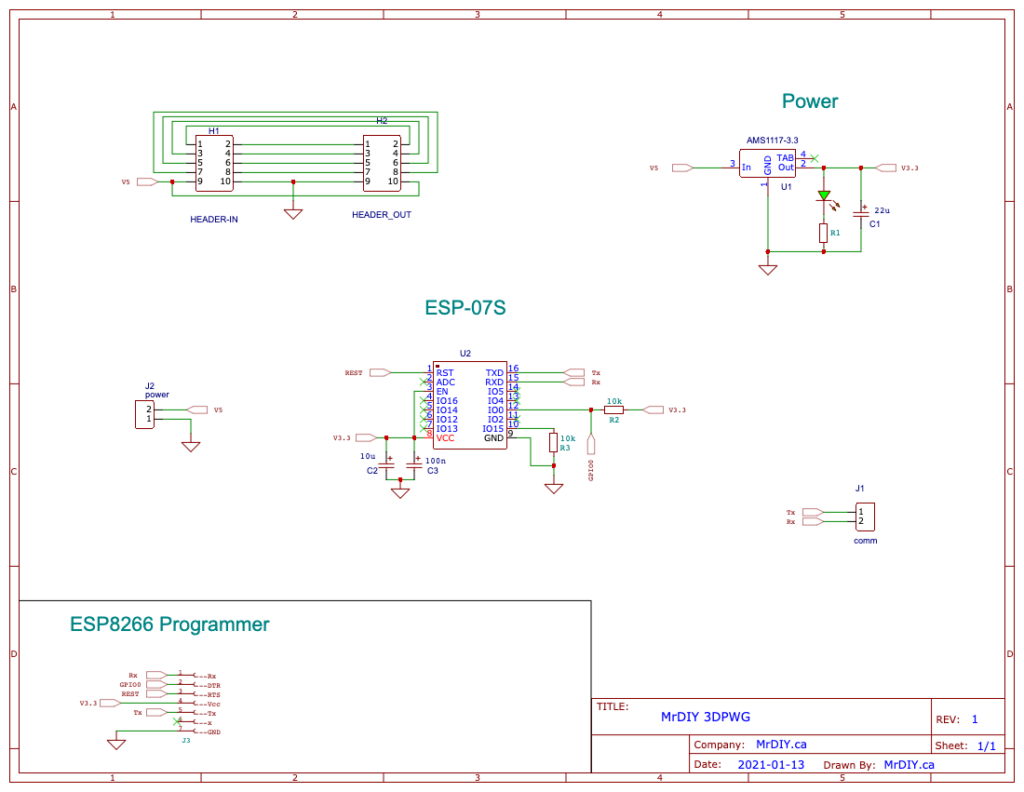
Schematic
To program ESP-07S/12F
The board already comes pre-flashed with the latest formware but if you need to manually flash it, you will need a FT232R USB to serial programmer (3.3V only). Check the back of the board for the programming pins and align it with the FT232R side pins (Tx, DTR, RTS, Vcc, Rx, Gnd). Then load the firmware or code as usual. No need to put the ESP in programming mode, the FT232R takes care of that.
Video overview
