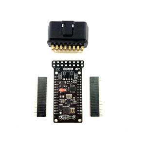
ESP32 CAN Bus Shield (v1.1)
$38.99
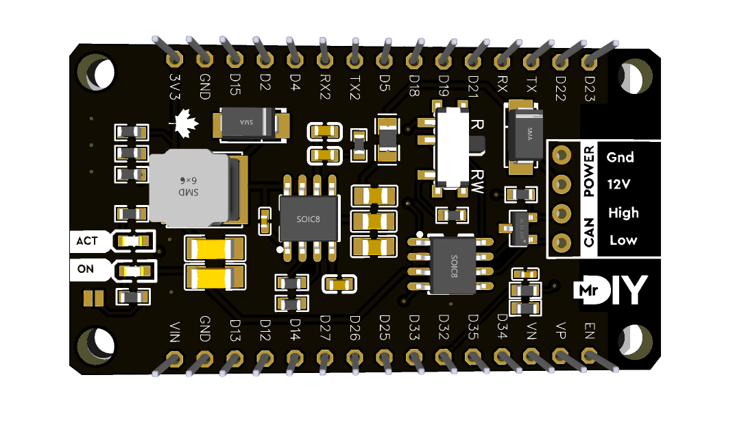
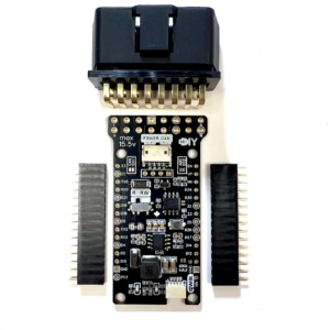
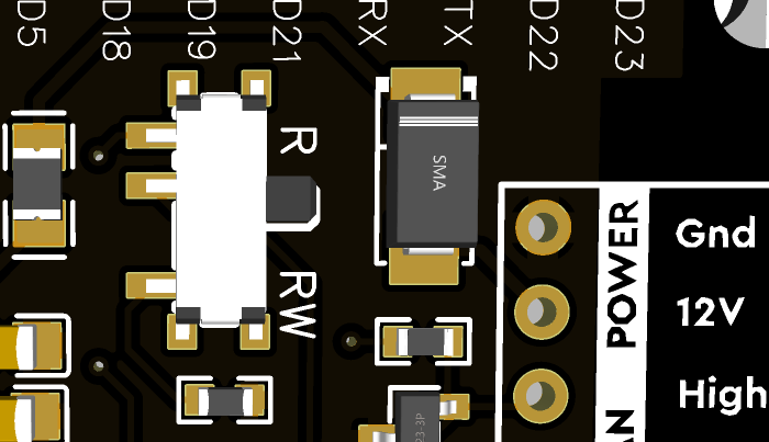
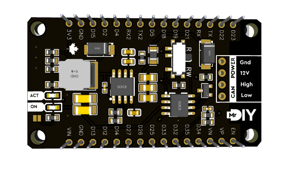
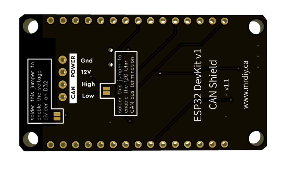
This is the upgraded (version 1.1) ESP32 CAN shield. This development kit has a CAN transceiver, 3.3V voltage regulator, red LED to indicate power, and blue LED connected to D26. New for v1.1, I added a voltage divider on D32, a 120Ω CAN termination resistor and a physical toggle switch that allows the CAN transceiver to go in Listen-only / Do-Not-Transmit mode.
Compatible with the 30 pin ESP32 DevKit V1 version ONLY. Add it to your cart here or get it from Amazon, AliExpress or your favourite electronic store.
The shield comes with male headers, JST XH2.54 header and a 4 wire cable. PS: the colours of the wires are arbitrary.
The original v1.0 page can be found here.
Out of stock
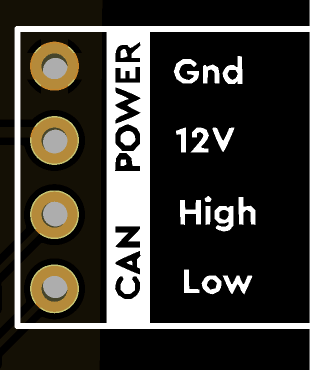
This is a custom, machine assembled, CAN shield designed to fit the 30 pin ESP32 DevKit1 board version. It uses the SN65HVD233 CAN transceiver and can be powered directly from a 12v power source (ex: a car battery).
CAN
|
Power
|
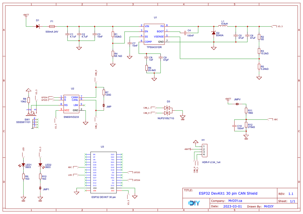
The red LED, voltage divider and 120Ω resistor are disabled by default and can be enabled by soldering solder-jumpers on the shield.
The SN65HVD233 CAN transceiver can be configured into 2 modes (using a physical toggle switch):
  |
|
Wiring
  |
|
Schematic



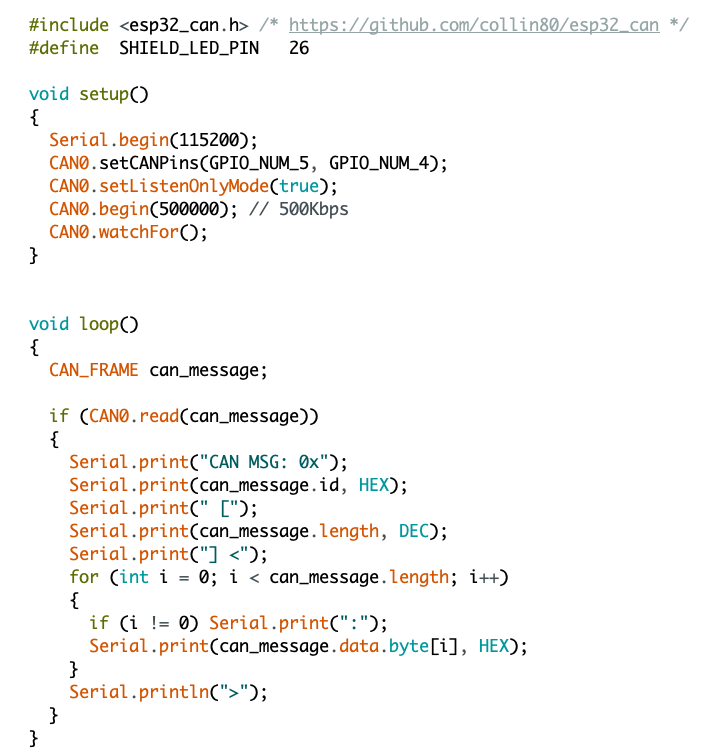
Sample Code (download code)

Video overview of the original v1.0

