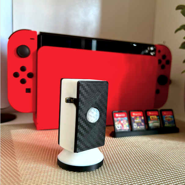
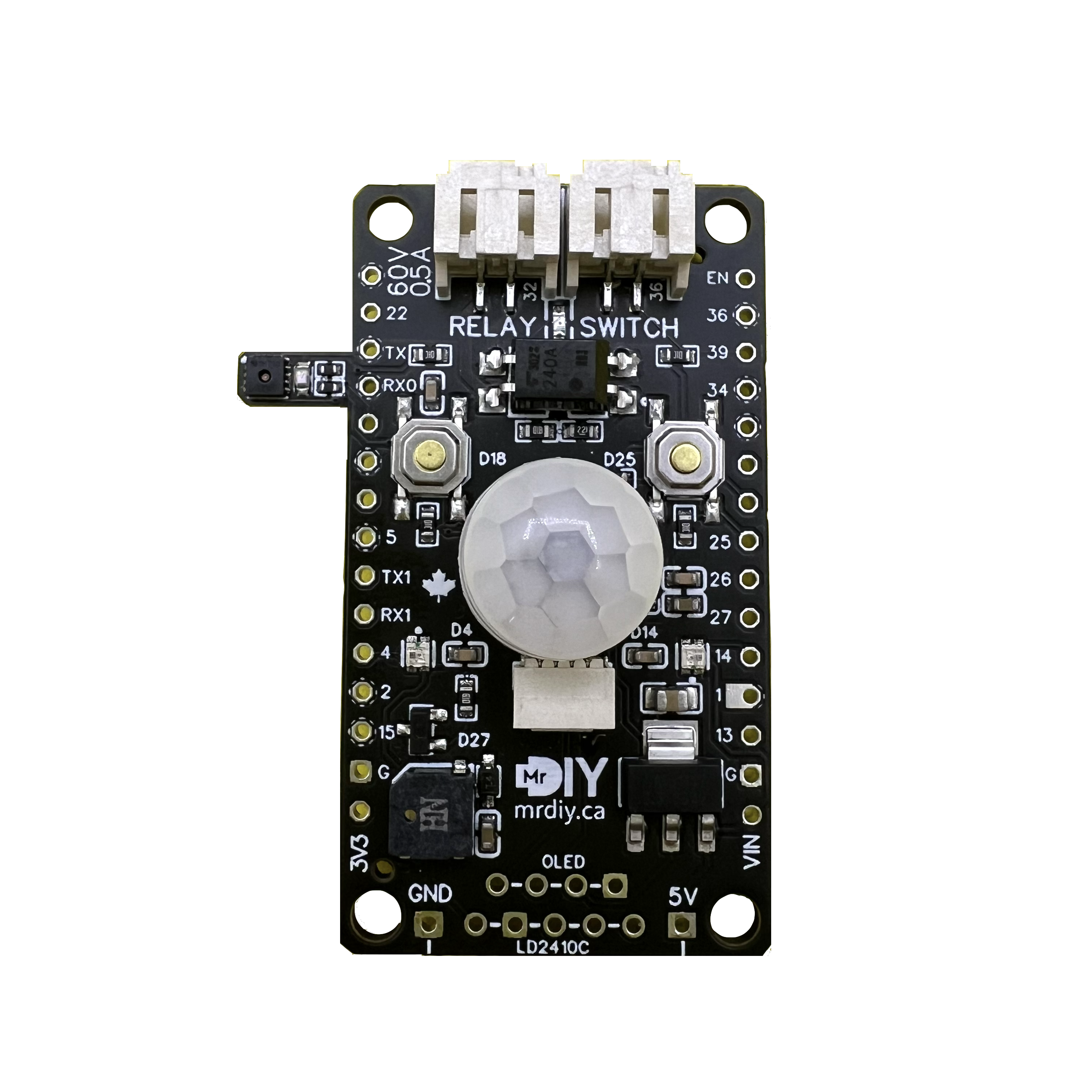
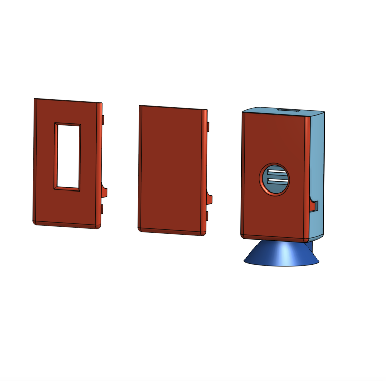
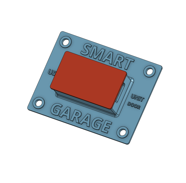
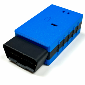
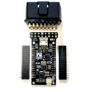
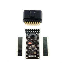
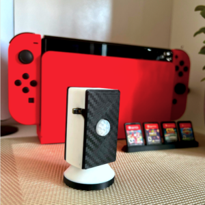
A plug-and-play board specifically designed for the 30-pin ESP32 DevKit 1 board, making it easy to bring your ideas to life quickly. Use it to build a multi-sensor room device, a garage door opener, a notification system, and much more. This compact shield includes over 10 sensors in one package, plus all the power of the ESP32 itself (Wi-Fi, Bluetooth, etc.).
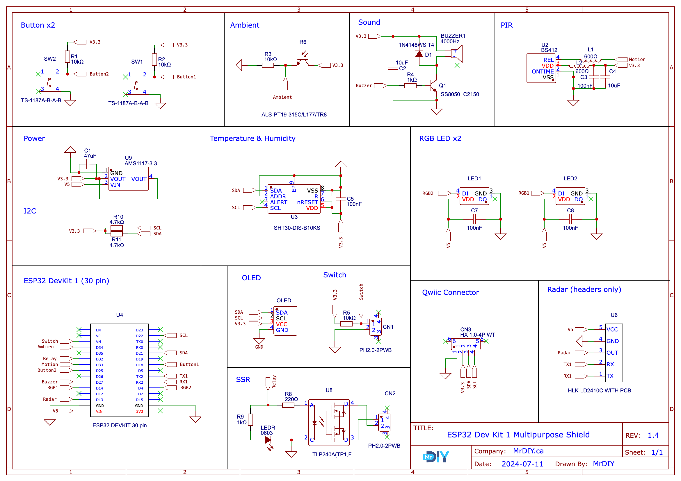
| Temperature & Humidity sensor | SHT30 | I2C – 0x44 |
| Ambient Light sensor | ALS-PT19-315C | GPIO34 |
| 2x RGB LEDs | WS2812B | GPIO04, GPIO14 |
| 2x General-purpose Buttons | Pulled High (3.3v) | GPIO18, GPIO25 |
| PIR sensor | BS412 | GPIO33 |
| Switch (input) | Pulled High (3.3v) | GPIO39 (JST PH2.0 connector) |
| Relay (low voltage) | TLP240A | GPIO32 (JST PH2.0 connector) Max. Input: 60Volt, 500mA |
| Micro Buzzer | MLT-5020 | GPIO27 |
| Headers for HLK-LD2410C | Not Included | RX:GPIO16 , TX:GPIO17, OUT: GPIO13 |
| Headers for I2C OLED (0.91″ or 0.96″) | Not Included | I2c (SDA, SCL, 3.3v and ground) |
| 3.3V Voltage regulator | AMS1117 | IN: ESP32 5V PIN OUT:3.3v – does not feed the ESP32 |
| Qwiic Connector | SparkFun | I2c (ground, 3.3v, SDA, SCL) |
| Extra GPIOs | Unused | 01 (TX), 02, 03 (RX), 05, 12, 15, 19, 26, 35 and 36 |
Schematic

ESPHome
You can configure and program the ESP32 using Arduino or ESPHome. For the best experience, try using ESPHome. Here are some sample configurations code:
ESPHome: base.yaml & with_radar.yaml


Applications
- Use the shield to create a comprehensive room sensor.
- Build a smart garage cover that automates and monitors your garage door.
- Set up alerts and notifications for various environmental conditions.
- Design an office desk panel to monitor and display relevant data.
- Develop a weather station to track and report local weather conditions.
- … and more
Notes
(1) for full disclosure: the temperature sensor may read higher due to its proximity to heat-generating components like the LDO, LD2410C or ES32. I’ve mitigated this with isolation and shielding, sticking the sensor outside the shield area and creating an offset variable in ESPHome which you can adjust. For more accuracy, consider adding another sensor using the unused GPIOs or the QWIIC connector.
Changes since v1.0
- Version 1.0: the original shield ( see video below)
- Version 1.1: replaced the temperature sensor with the SHT30 and moved it outside the shield area, added PH2.0 connectors, a 3.3V regulator, headers for the HLK-LD2410C, and removed the EEPROM and SD Card
- Version 1.2: major PCB re-routing ( did not assemble this version)
- Version 1.3: added a QWIIC connector, replaced the buzzer with a smaller footprint package, improved the PIR circuitry, corrected an error with one of the input pins, refined the PCB layout, text, and routing, and added an external pull-up resistor for the switch.
- Version 1.4 (this): minor PCB and text changes.
Video Overview [for the old version 1.0]
(*) are affiliate links.
