How to use:
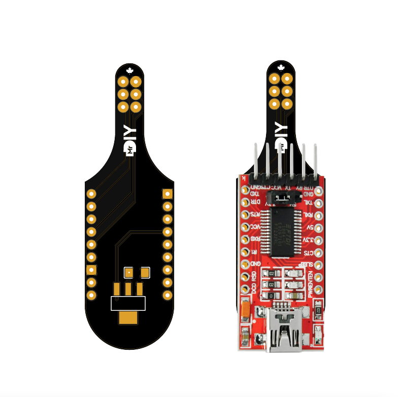
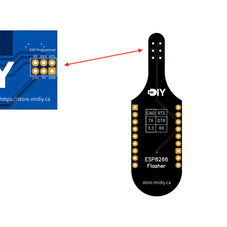
1) Solder an FT232R USB-to-serial adapter to the PCB as show below ( make sure FT232R is on the 3.3v jumper and not 5v).
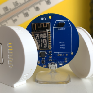
2) Align the 6 pins from the flasher PCB to the device. The pin labels are on the bottom of the PCB.
3) Flash as you would normally with an FT232R USB-to-serial adapter.
At the top of the PCB, there are spots for a 3.3v regulator and a capacitor. Normally, they are not needed. I ran in some scenarios that more current is required to program an ESP8266. I added this for those rare scenarios.