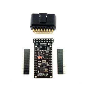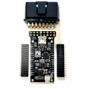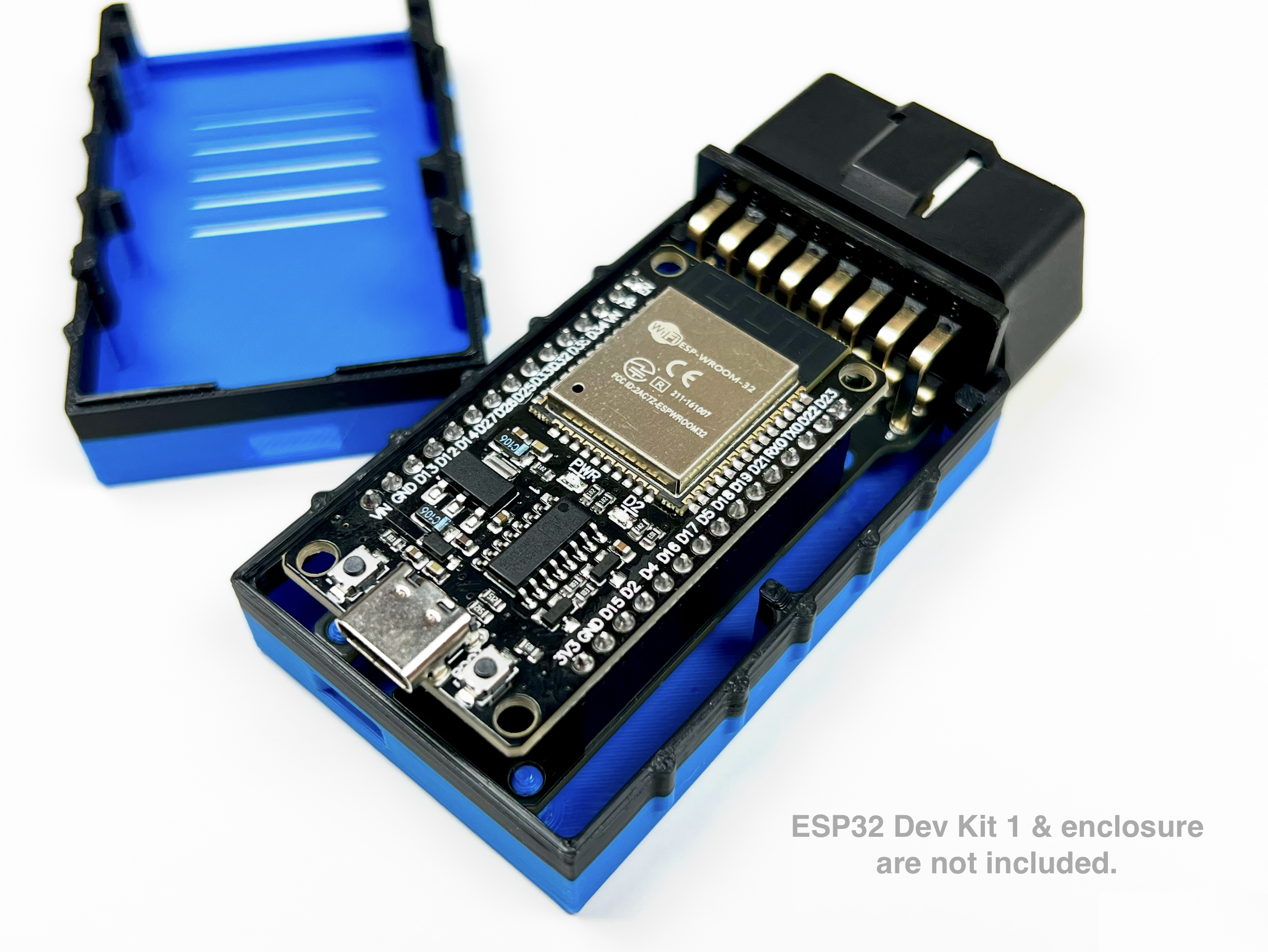

This custom CAN shield is designed to fit the 30-pin ESP32 DevKit1 board version and comes equipped with a CAN transceiver. It can operate on power ranging from 7 to 15.5 volts, allowing direct connection to a car battery, thanks to its efficient buck converter. The shield includes two general-purpose LEDs, a button, and a qwicc connector, offering great versatility and expandability.
CAN Communication
The shield complements the ESP32 CAN controller by adding a CAN transceiver offering:
- Data Rates: up to 1 Mbps
- Compatible With ISO 11898-2
- Cross-wire protection
- Over temperature (thermal shutdown) protection
- EMI and ESD bus protection using NUP2105
- Loop-back (LBK) feature is available on GPIO33 (active HIGH)

- In your code use: Rx = D4 and Tx = D5
Power Management
The shield can be efficiently powered by 12V automotive source through its onboard buck converter, offering:
- Max Input Voltage:
- without enabling the voltage divider: 24 Volt
- with the voltage divider enabled: 15.5 Volt
- Max Input Current: 2 Amp
- Frequency: 570 kHz
- Outputs 3.3V to the ESP32 board
- Overvoltage transient protection
- Thermal shutdown protection
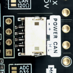
120Ω & ADC Features
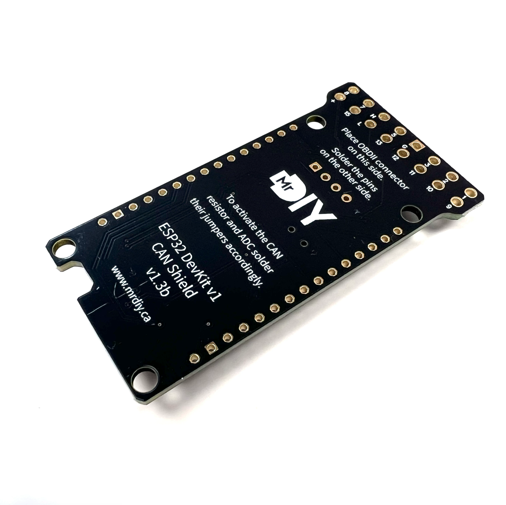
By default, the shield comes with a voltage divider on GPIO32 and a 120Ω CAN termination resistor disabled. These features can be activated by soldering solder-jumpers on the shield, labeled ‘ADC D32’ and ‘CAN 120’ respectively.
LEDs
The shield offers two LEDs connected to GPIO26 and GPIO27 for general use.
Button ![]()
The shield is equipped with a low profile push button connected to GPIO25 (with a pull-up resistor) for general use.
Expandable ![]()
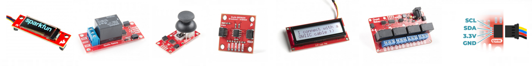
In version 1.3, the shield adds a new Qwiic connector, enabling you to expand its functionality with qwiic accessory boards (e.g. OLED screen, relay, SDCard OpenLog, RGB LED, or your own DIY board using a 4p-reverse cable). For a complete list of qwiic accessories, visit SparkFun’s website.
Please note: The shield includes a solder jumper to enable the I2C pull-up resistors (disabled by default).
Modes
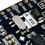
The shield provides two operational modes: R and RW. You can switch between them using the physical toggle switch:
 |
|
Wiring
You can connect the shield either via the OBDII connector (most cars) or manually with a JST plug. Both methods are wired together, so you should avoid using them simultaneously.
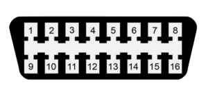 |
OBDII
|
 |
ZH1.5 4-pin socket
|
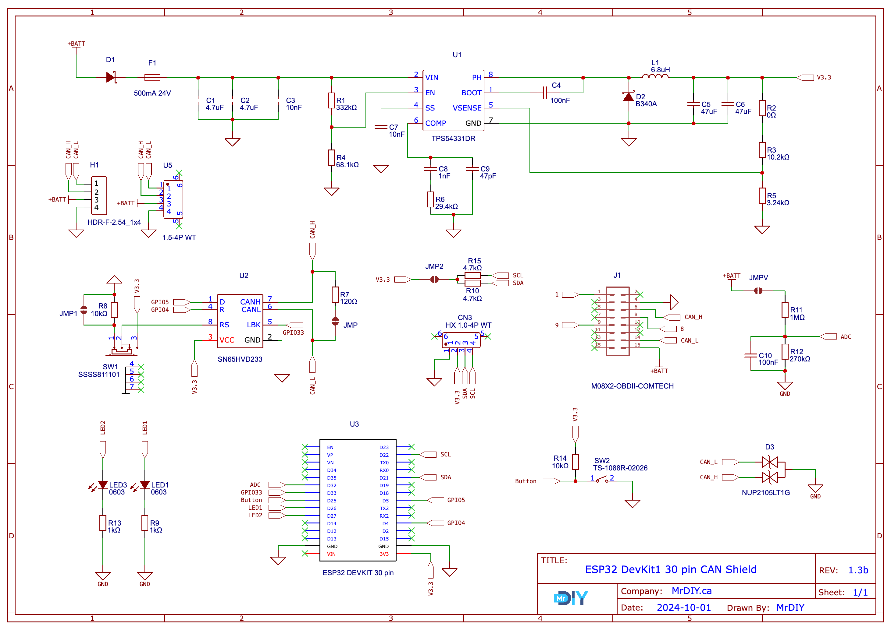
Schematic
Programming
You have the option to code the ESP32 directly with:
- The Espressif IoT Development Framework
- Espressif calls CAN‘ TWAI‘ (Two Wire Automotive Interface)
- In your code use: Rx = GPIO4 and Tx = GPIO5
- Arduino using one of the following:
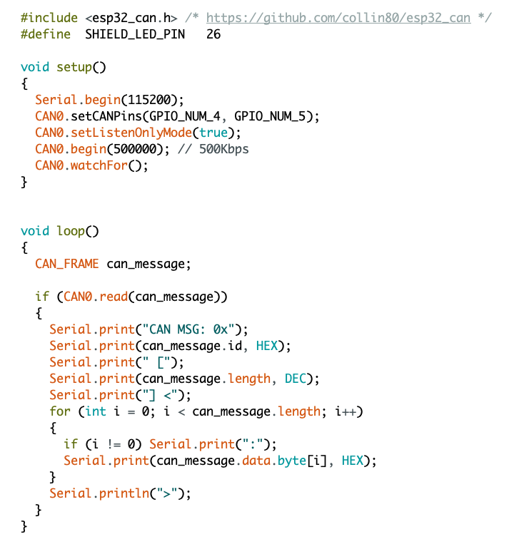
- Collin Kidder’s ESP32-CAN library – [sample code]
- Sandeep Mistry’s Arduino-CAN library
- Espressif’s TWAI API – [sample code]
- Collin Kidder’s ESP32-CAN library – [sample code]
- You can also use SavvyCAN directly with the shield by flashing the ESP32RET firmware onto the ESP32 [EXPERIMENTAL] . You can flash the ESP32RET source code directly or by using my online flasher. Watch this video for more details.
Change Log
- Version 1.0: the original shield
- Version 1.1: added a voltage divider on GPIO32, a 120Ω CAN termination resistor, and a physical toggle switch enabling the CAN transceiver to toggle between “Listen-only” and “Do-Not-Transmit” modes.
- Version 1.2: added an OBD2 connector pinout, an extra LED on GPIO27, layout improvement, larger text, relocation of solder-jumpers to the top side, and the creation of a custom 3D printable case.
- Version 1.3: added a general purpose button to D25, added a Qwiic connector to be used with sparkfun qwiic modules, made several modifications to the CAN transceiver: (1) eliminated the dominant state at boot, (2) connected the LBK pin to D33, (3) added a solder jumper for high-speed mode, and (4) swapped D4 & D5 pins, removed the always-on red LED, made PCB improvements, and updated the custom 3D printable case.
- Version 1.3b (this): replaced the 4 holes for an optional JST XH2.54 adapter with a permanent JST ZH1.5 4-pin socket.
Disclaimers
* links are affiliate.
** altering the CAN bus or modifying its data flow can disrupt vehicle operations, potentially leading to unintended behaviour, damage, serious technical issues, voiding warranties, and possibly violating legal regulations. Ensure compliance with local laws and vehicle manufacturer guidelines before making any changes to the CAN system.