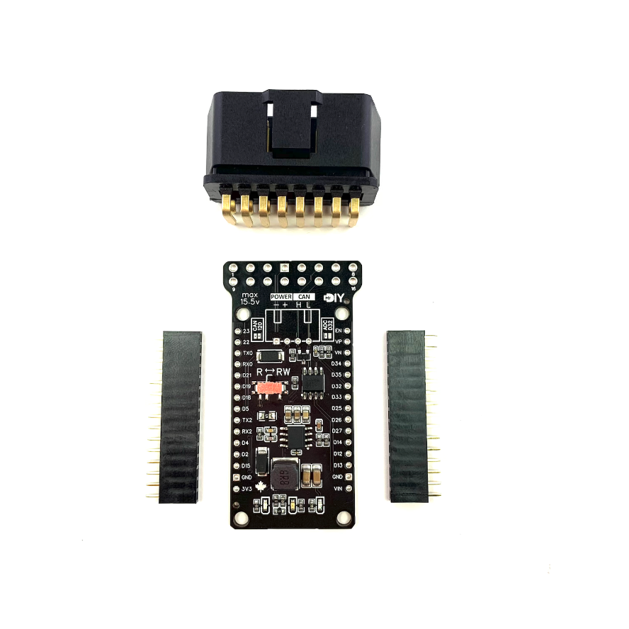
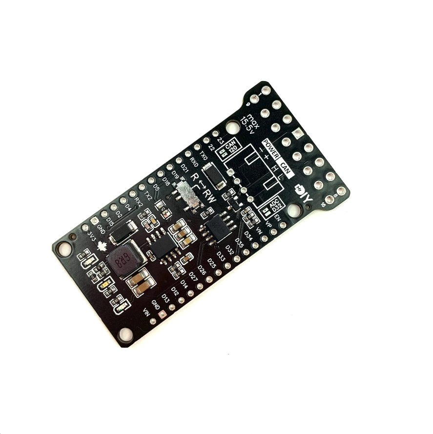
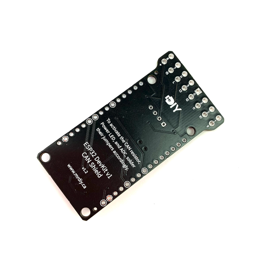
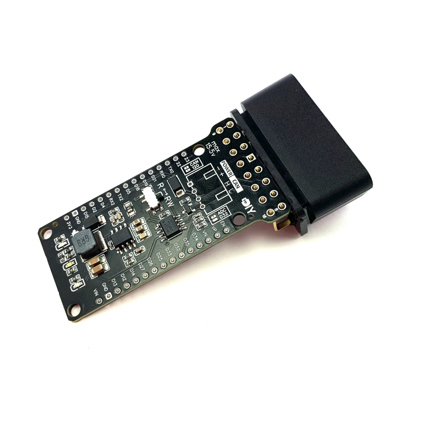
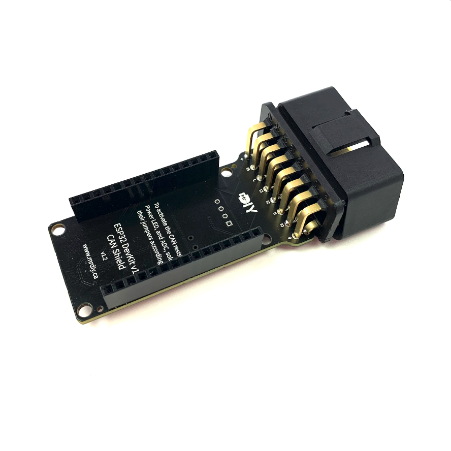
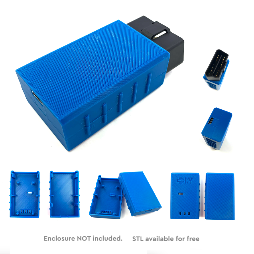
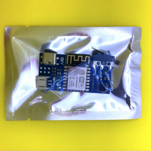
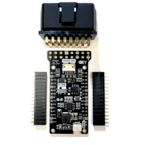
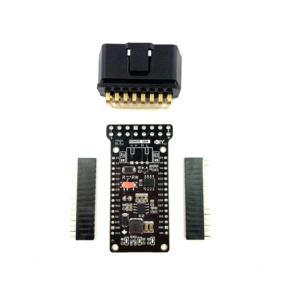
This is a custom, machine assembled, CAN shield designed to fit the 30 pin ESP32 DevKit1 board version. It is equipped with a CAN transceiver. This shield can operate with power ranging from 7 volts to 15.5 volts, which means you can connect it directly to a car battery thanks an efficient buck converter.
CAN
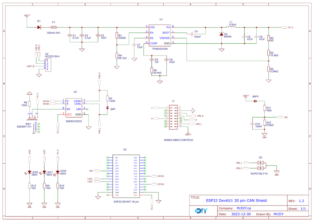
The shield complements the ESP32 CAN controller by adding a CAN transceiver offering:
- Data Rates: up to 1 Mbps
- Compatible With ISO 11898-2
- Cross-wire protection
- Over temperature (thermal shutdown) protection
- EMI and ESD bus protection using NUP2105
- In your code use: Rx = D5 and Tx = D4
Power
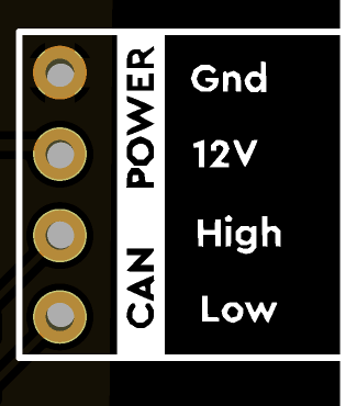
The shield can be efficiently powered by 12V automotive source through its onboard buck converter, offering:
- Max Input Voltage:
- without enabling the voltage divider: 24 Volt
- with the voltage divider enabled: 15.5 Volt
- Max Input Current: 2 Amp
- Frequency: 570 kHz
- Outputs 3.3V to the ESP32 board
- Overvoltage transient protection
- Thermal shutdown protection
120Ω & ADC Features
By default, the shield comes with a voltage divider on GPIO32 and a 120Ω CAN termination resistor disabled. These features can be activated by soldering solder-jumpers on the shield, labeled ‘ADC D32’ and ‘CAN 120’ respectively.
LEDs
The shield includes three LEDs. The first is a Red LED, which is always on when the shield is powered. The second and third LEDs are Blue and Green and are connected to GPIO26 and GPIO27 for general usage.
Modes
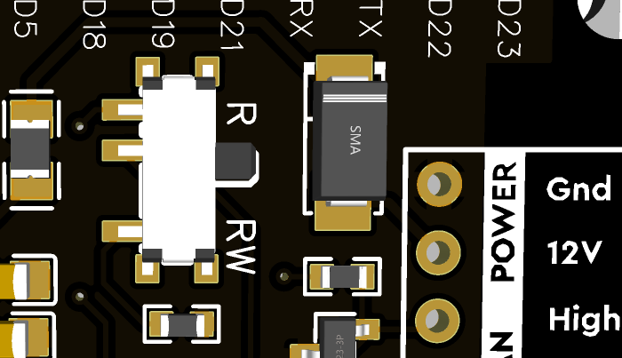
The shield offers two operational modes: RW and R. Toggle between these modes using a physical switch:
  |
|
Important: In RW mode, hot plugging the ESP32 forces the CAN transceiver into a dominant state during boot (~300ms). During this time, no devices on the CAN bus can transmit, and other CAN controllers may send error frames or increment their error counters. However, this condition resolves once the ESP32 has fully booted. If you’re using this shield for troubleshooting or active monitoring, a quick workaround is to connect the USB to the ESP32 for power before hot plugging it into the CAN bus/OBDII port. RW mode is not recommended for permanent installations. On the other hand, R mode is unaffected, as the transceiver remains in read-only mode, making it safe for permanent OBDII installations. That being said, if you really need to stop the shield from entering a dominant state when hot-plugged in, you can perform this D4Mod.
Wiring
  |
|
OBDII
  |
|
Schematic
Programming
You have the option to code the ESP32 directly with:
- Espressif IoT Development Framework – TWAI (Two Wire Automotive Interface) [Advanced]
- Arduino using one of the following:
- Sandeep Mistry’s Arduino-CAN library
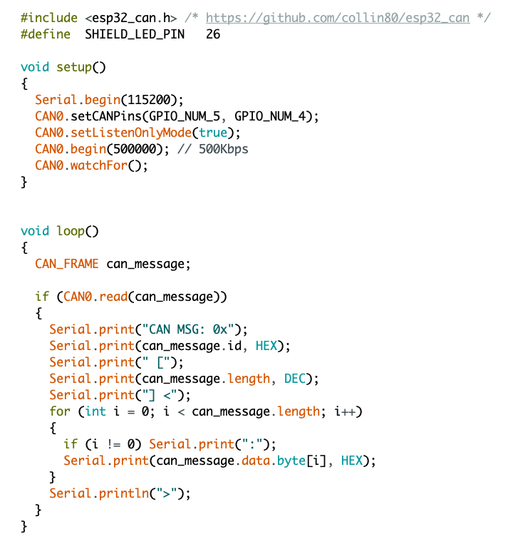
- Collin Kidder’s ESP32-CAN library – [sample code]
- Espressif’s TWAI API – [sample code]
- [EXPERIMENTAL] You can also use SavvyCAN directly with the shield by flashing the ESP32RET firmware onto the ESP32 using my online flasher. Watch this video for more details.
Reminder: The shield uses D5 for CAN_RX and D4 for CAN_TX.
Arduino [ESP32-CAN sample code]

Changes since v1.0
- Version 1.0: the original shield
- Version 1.1: added a voltage divider on GPIO32, a 120Ω CAN termination resistor, and a physical toggle switch enabling the CAN transceiver to toggle between “Listen-only” and “Do-Not-Transmit” modes.
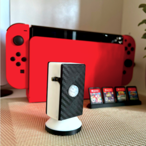
- Version 1.2 (this): added an OBD2 connector pinout, an extra LED on GPIO27, layout improvement, larger text, relocation of solder-jumpers to the top side, and the creation of a custom 3D printable case.
(*) are affiliate links.
