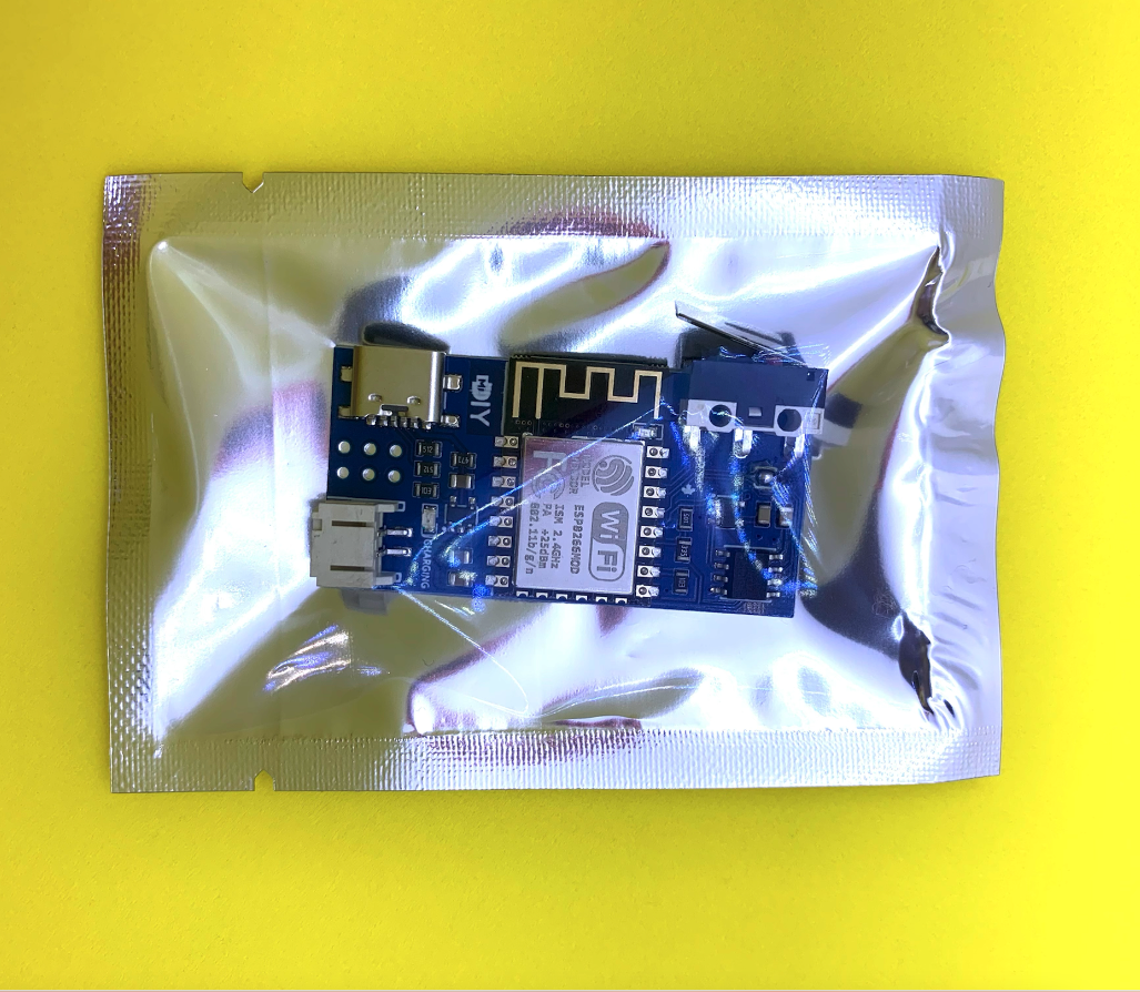
This is the third iteration of my contact sensor. I designed this sensor because I had a need for a wireless, non-proprietary, cloud-free doors/windows sensor. Unlike a button sensor, which is simpler to design, a contact sensor needs to trigger on both ON and OFF states. I optimized the design to use small Lipo batteries and picked components, like the LDO, to be efficient and are low in power consumption in both active and standby modes. The ESP8266 module spends the majority of its time completely off consuming no current. The ATtiny stays in deep sleep until the switch status changes. The sensor can be paired with an ESPNow hub to minimize the sensor’s uptime using ESPNow. This enables a ~150ms trigger time needing <50mA on average. The sensor has a ~5μA standby current.
RevB has visible battery polarity text (+/-) on the PCB and two extra pull-up resistors (GPIO0 & GPIO2).
Standby current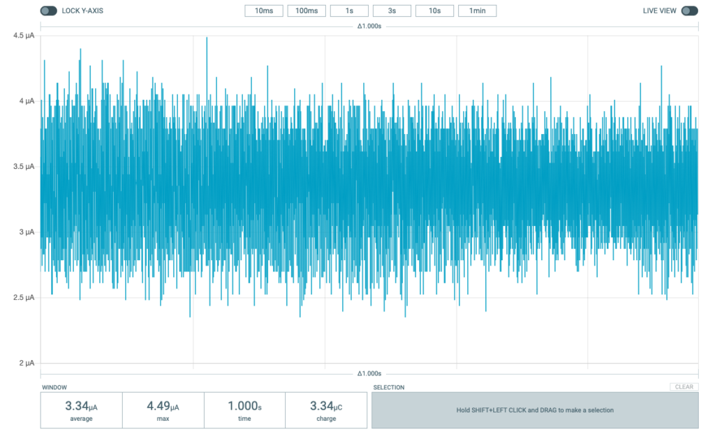 |
Trigger duration & consumption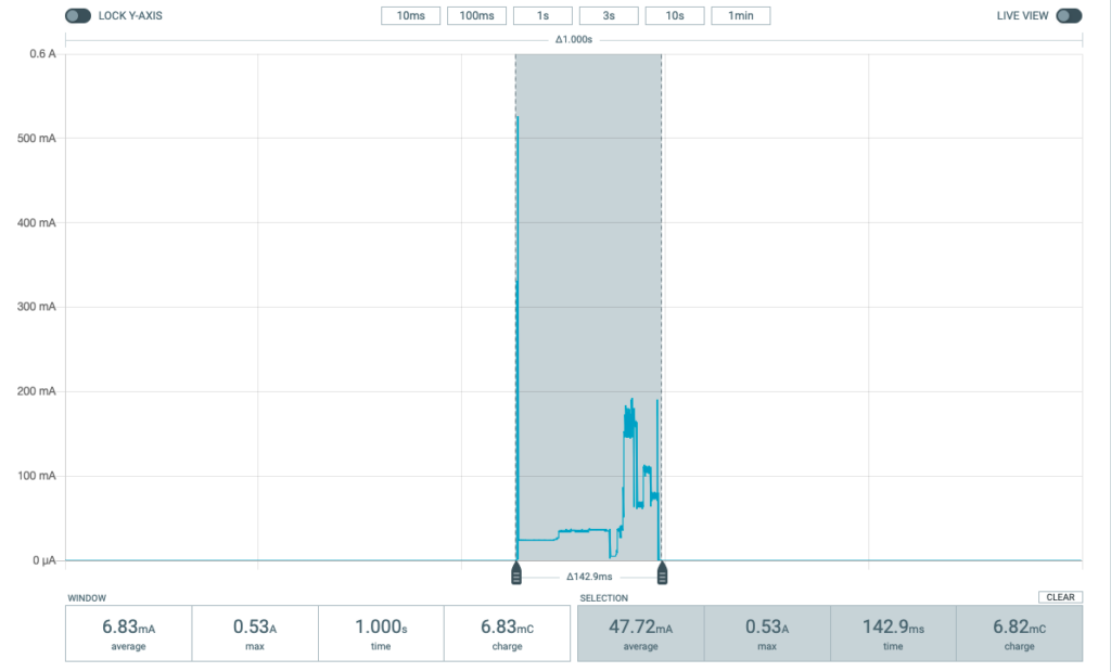 |
In Action
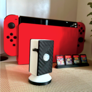
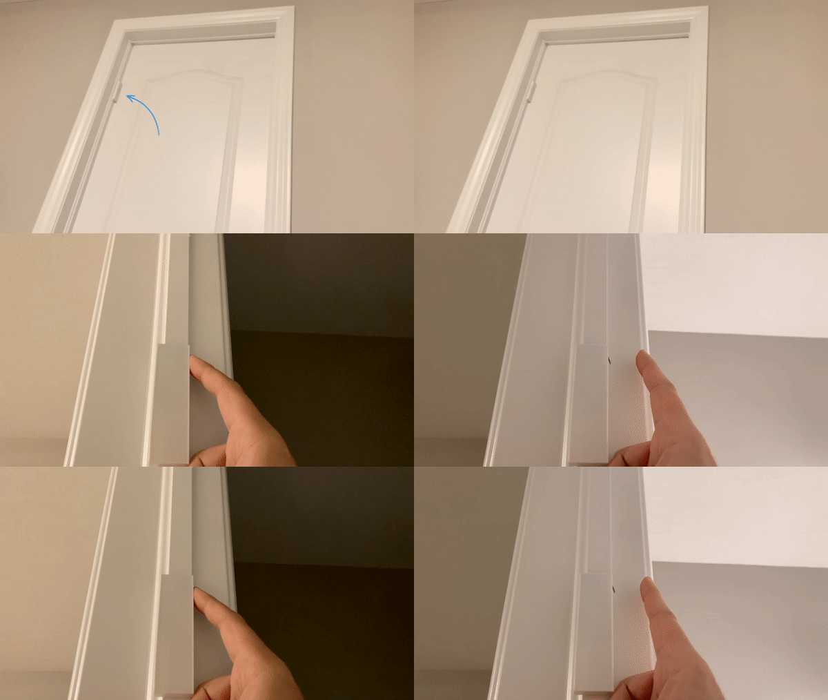
I used it as a door sensor along with the hub to send MQTT updates to a home automation system. The home automation system turns the smart light on or off depending on the door status.
Battery
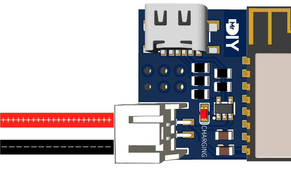 The sensor has been designed and tested with single cell 3.7 Volt Li-Ion/Li-Polymer batteries. It uses a JST PH2.0 as the battery plug. It has a built-in Lithium battery charger using MCP73831 which is a miniature single-cell, fully integrated Li-Ion, Li-Polymer charge management controller. To charge the battery, connect a USB-C cable from a static 5V source or a USB-C Power Delivery adapter. A red LED will turn ON while the battery is charging and turn OFF when it is fully charged.
Here are some very rough estimates to provide a sense on how long a 400mAh would last:
- In stand by = 400mAh/5μA = 400,000μAh/5μA = 80,000h ~= 9 years
- Each trigger consumes 50mA * 0.15s/60/60 = 50mA * 0.00004h = 0.002mAh
- Number of triggers per full charge = 400mAh / 0.002mAh = 20,000 triggers
- These numbers don’t take into consideration the battery self discharge.
- If I have to guess, a more realistic number would be 2-3 years of battery life with a ~50 triggers a day.
- DO NOT plug the USB-C charging cable when using the sensor with non-rechargable or non Li-Ion/LiPo batteries.
- UPDATE: Make sure the sensor is not triggered excessively/multiple times a second, for example, by pushing and releasing the micro-switch very rapidly. I discovered that the ESP8266 will go into an unstable state consuming a lot of power (50mA) until it drains the battery. If this happens, unplug and re-plug the battery.
Source Code
The sensor already comes pre-flashed with the latest firmware. The complete source code is available on my Gitlab repository.
Two ways to program the ESP-12F:
1) Using a FT232R USB-to-serial programmer (3.3V). Connect the 6 pins from the sensor to the FT232R adapter ( using the SIDE pins not the 6 pins at the bottom of the FT232R adapter). You can find the sensor’s programming pins labels on the back of the sensors. No need to put the ESP in programming mode since the FT232R takes care of that when you use all 6 pins. Please make sure the battery is disconnected before flashing the ESP8266.
2) Get my custom FT232R adapter companion PCB. No need to put the ESP in programming mode since the FT232R takes care of that if you use all 6 pins. Please make sure the battery is disconnected before flashing the ESP8266.
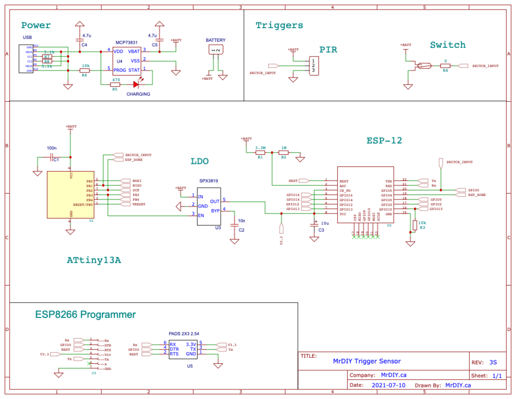
Schematic
The Hub
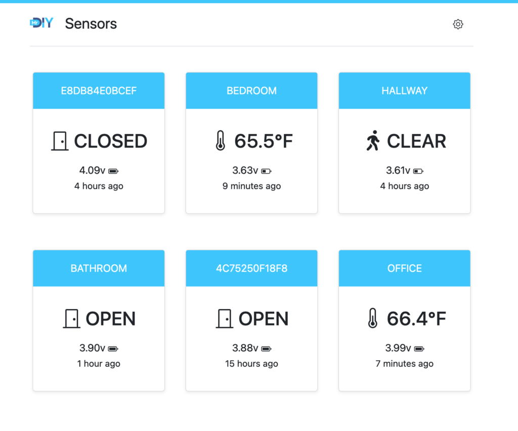
The sensor can be used to send updates directly over Wi-Fi but, if you want to unleash its full potentials or get the instant response time and long battery life, you will want to pair it with the Hub. You can read more about the Hub here. Here is a preview of the Hub interface.
YouTube Video
